Please correct my assumptions, I'm struggling with this silly IC...
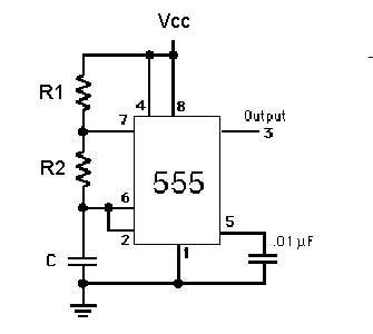
pin 3 goes out to whatever I want the on/off pulse to hit(an led/transistor/mosfet/etc.)
pins 2 & 6 are connected together with a capacitor(C) going to ground and R2
R2 connects the pin 2,6,C to pin 7
R1 connects pin 7 to pins 4,8,+V
So does this diagram work?

and why are pins 8,4,7 seemingly connected?
and why are pins 7,6,2 seemingly connected?
how does pin 4 force pin 3 low if pulled to ground? and even though pin 5 isn't used here...how can it be used to adjust threshold trigger voltage, when pin 6 is the threshold pin?

